Magnetic Stripe Reader Teardown
Jul 28, 2018 “My experiences disassembling a cheap magnetic card reader/writer.”#reverse engineering #floss #hardware #MSR605X
In April, I started reverse engineering the MSR605X magnetic stripe reader. Progress has basically paused at this point as I handle other affairs, but I figured that I may as well document what I have learned so far. My code for this little project is on Gitlab.
This post won’t describe how magstripe readers work. If you’re interested, Major Malfunction gave an excellent in-depth talk on the subject. For this post, we only need to know that chip on the magstripe reader measures some stuff and sends us some bytes via USB.
Hardware
I’ve never reverse engineered a peripheral before, so this project seemed quite daunting at first. I have very little background in physical electronics, and I’ve mostly been learning as I go with this project. I’m a software guy, so I figured that I could just substitute my lack of understanding of the hardware with really smart software.
Exterior
The exterior of the device is just plain plastic. There is a (assuredly fake) FCC compliance sticker as well as a barcode. One nice touch about this reader is that it came with two gel pads to keep it from sliding. This is throwaway tech from Shenzen, so I don’t expect too much in terms of build quality.
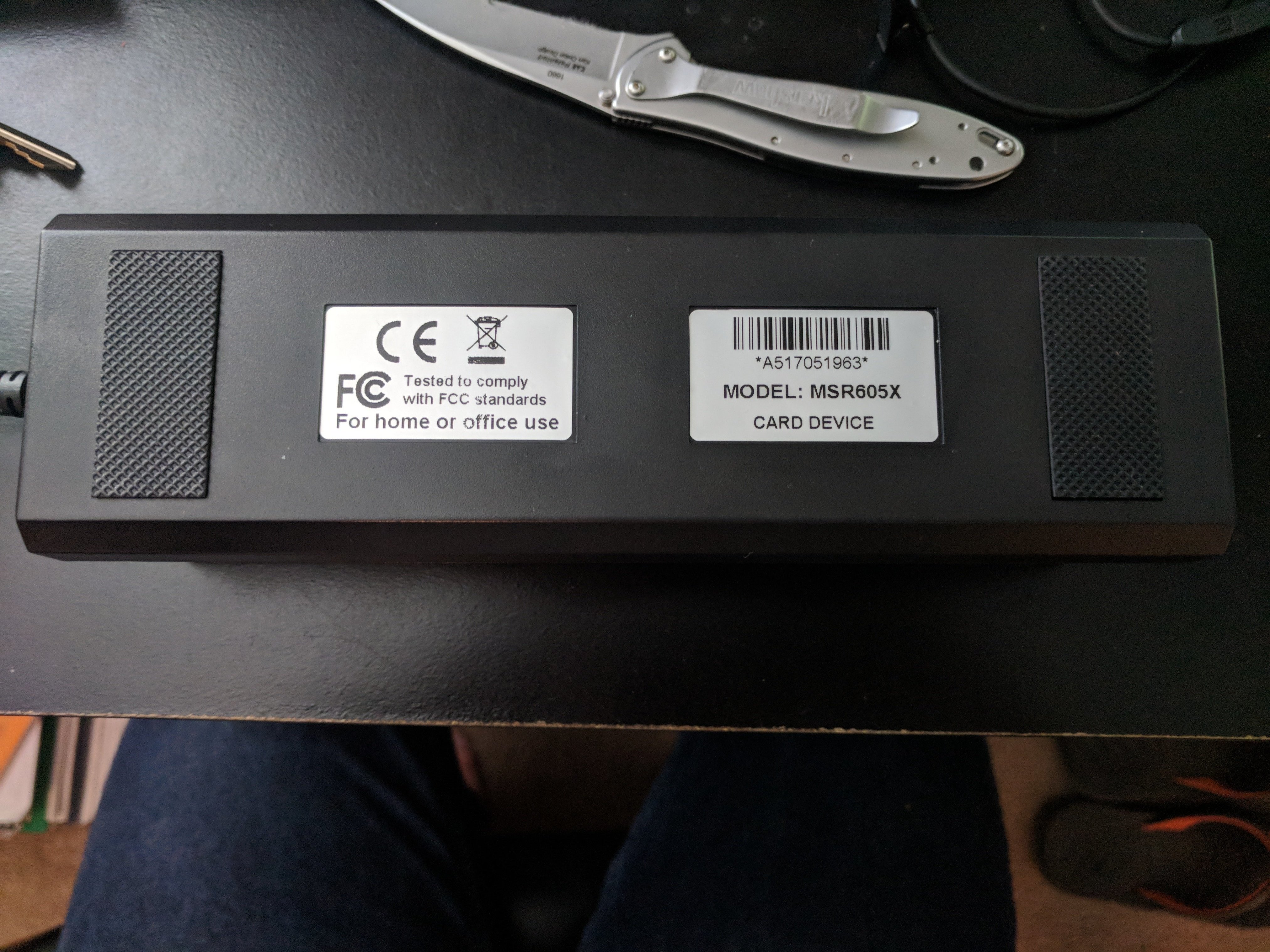
Bottom side of the MSR605X.
Interior
The interior of the reader is pretty simple as well. It consists of a metal plate (which gives the unit most of its weight), a small battery, a logic board, as well as a support structure for the parts of the card which actually interact with the cards (i.e. the magnetic bits).
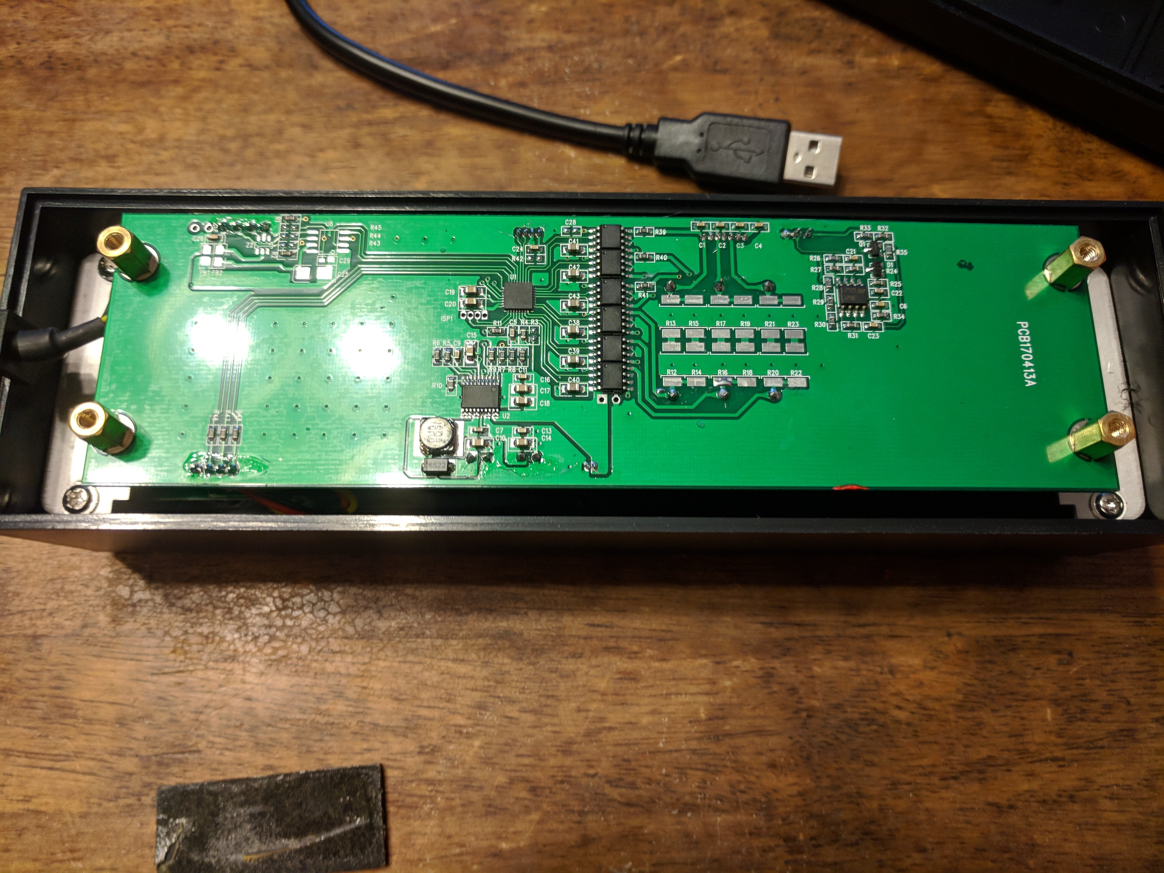
Overview of the reader's PCB.
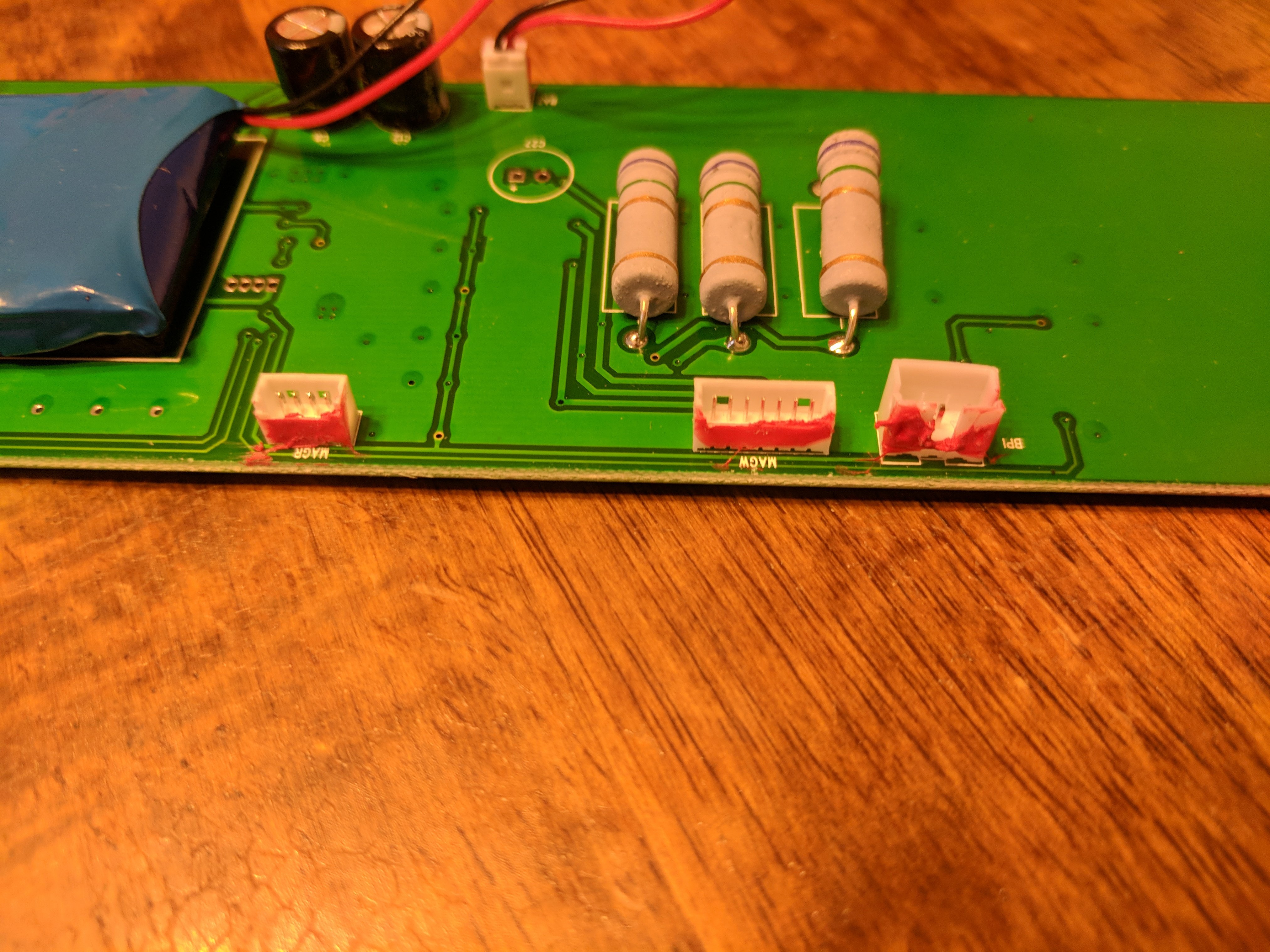
Labeled JST-like connectors.
All of the components not directly soldered to the motherboard are connected with JST-like connectors.
Electronics
Now for the actual meat of the reader. There are a few headers labeled on the PCB. These headers are: MAGW, MAGR, BPI, XPI, LED0, and BAT. As you can probably guess, they are connected as follows:
MAGW- (Magnetotron?) Writes data to card.MAGR- 3-Track card readerBPI- (Motor?) Detects speed of swipeXPI- USB cable to hostLED0- Status LEDs (red, yellow, green)BAT- On-board battery (which functions as a capacitor)
The central microcontroller is a Silicon Labs Universal Bee 2, 32-bit chip (EFM8 UB20F32G) in a 32-pin QFP package. Pins #9 and #10 (used in SI’s C2 Debugging Protocol) are connected to a pair of solder pads labeled ISP1 (presumably for debugging and In-System-Programming). I currently don’t own a universal programmer, so dumping the chip’s firmware was not an option.
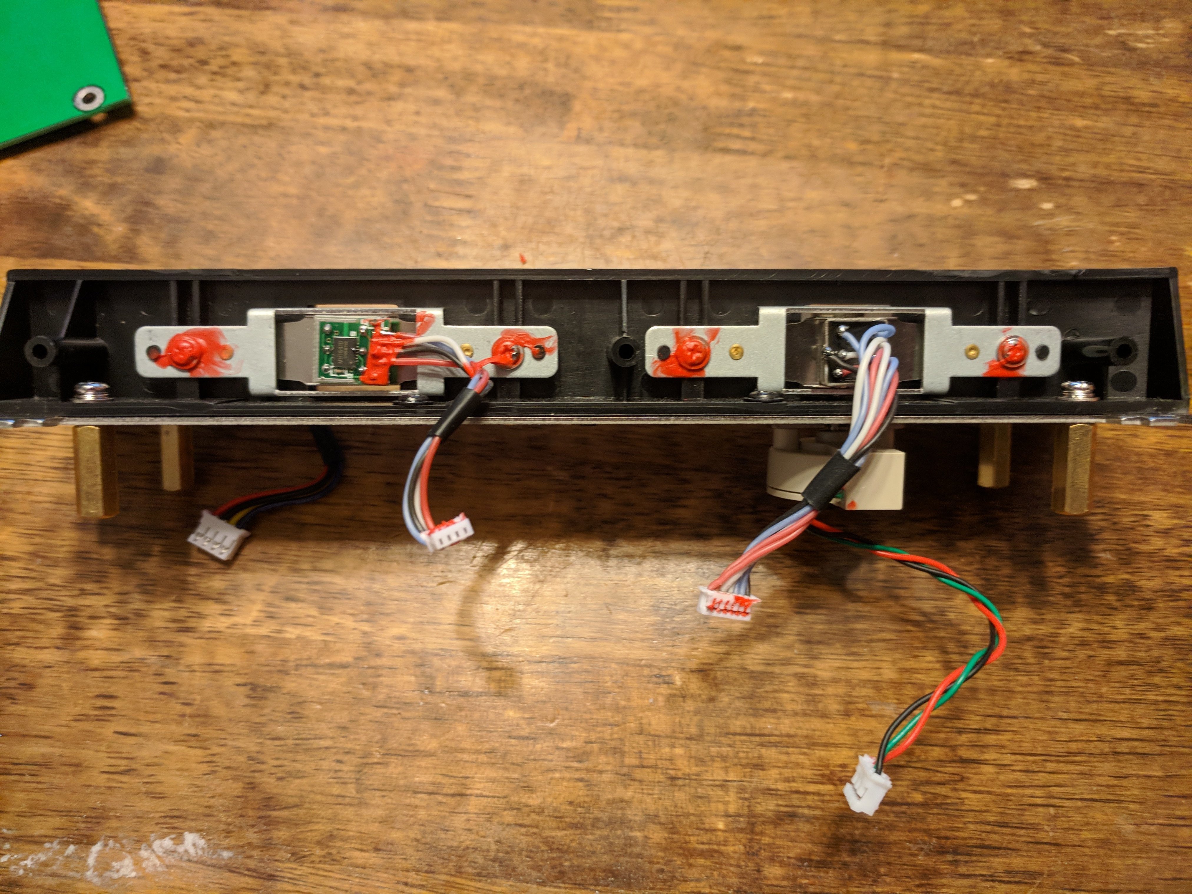
Side view of the slot where a magnetic card goes.
Connected to MAGW which (I assume) writes the cards are six MX612E motor drivers. Connected to the BPI jack is a single TL06C JFET amplifier; presumably this is used to measure how quickly a card is passing through the magstripe reader’s slot.
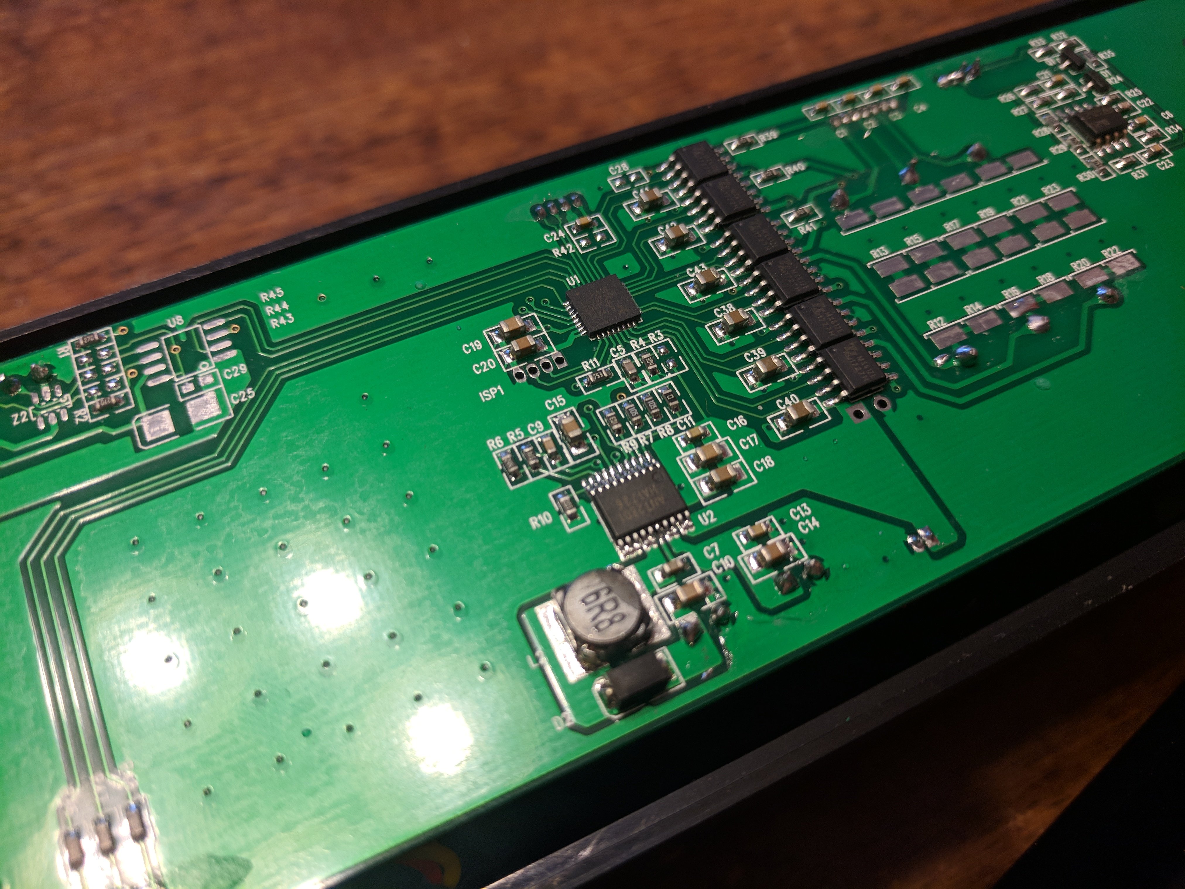
Another shot of the PCB. You can read some of the chip markings here.
Moreover, there is also a battery driver (part number ANT2801) connected to the battery on the underside of the PCB. I suspect that it’s being use as a (big) capacity in this device.
Software
On the software side, the MSR605X has a very similar protocol to its predecessor, the MSR605. The difference here is that instead of using a PL2303 serial-to-usb adapter, the MSR605X just pretends to be a USB HID device, and uses HID as a wrapper for the original serial-based protocol. This allows the MSR605X to use (nearly) the same protocol as its serial-based predecessors. Because of this, I was able to reference existing libraries for the MSR series, and modified the device commands as needed.
I’ll be going into the specifics of the software and communication protocol in another post. Just know that for now the software was half reverse engineered, and half reused code. After spending a few hours in a disassembler, it became pretty obvious what the software was doing.